Einleitung

Lässt sich deine Kamera auch mit einem neuen Akku nicht mehr einschalten? Werden die Bilder nicht mehr richtig gespeichert? Eventuell hilft ein Austausch der Hauptplatine.

  1. BxPhxv5RcJCniZEC
    BxPhxv5RcJCniZEC
    24qG21PMoPF15qTP
    bFoIAGf2cKngBUWn
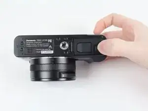
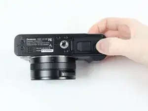
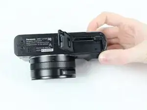
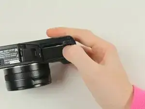
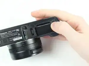
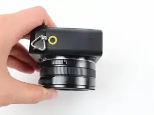
    • Lege die Kamera mit dem Boden nach oben hin. Drücke den OPEN/LOCK Schieber in die OPEN Position.

    • Die Klappe über dem Akkufach sollte sich öffnen.

  2. cBlsvJMuCeuhuPtd
    cBlsvJMuCeuhuPtd
    UbCCpay2LH1tquto
    • Drücke den inneren Schalter nach oben, um den Akku zu lösen.

  3. nIDnaFMiZ3kI64Po
    • Fasse den Akku am Rand an und ziehe ihn heraus.

    • Ersetze ihn durch einen LUMIX Panasonic DMW-BLE9PP Akku.

    How to take off the battery housing door? Is it necessary to take the front cover off in order to do it?

    Boser Hund -

    Hello, how to take the battery housing door off on lx100? Is taking the front cover off necessary? The whole tutorial is great but the most common part that breaks often is not covered.

    Boser Hund -

  4. i5GO6TVIDIAZVyq5
    i5GO6TVIDIAZVyq5
    eAhZCZDBGBUWH21H
    FHeIwipHxv5L3VCm
    • Manche dieser Schrauben sind mit einem Kleber gesichert, um zu verhindern, dass die Kamera zerlegt wird. Drücke beim Herausdrehen fest auf den Schraubendreher und arbeite langsam, damit die Schraubenköpfe nicht beschädigt werden.

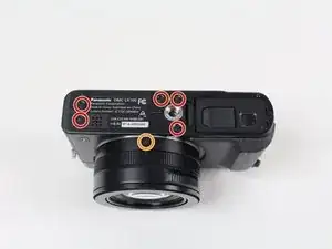
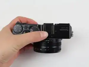
    • Lege die Kamera so, dass der Boden oben ist und das Objektiv zu dir zeigt. Entferne die fünf 4,5 mm Kreuzschlitzschrauben #000 unten an der Kamera und die obere Schraube auf der linken Seite.

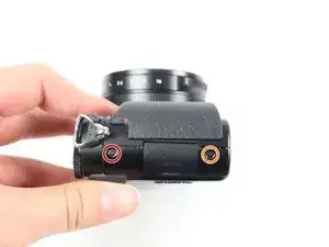
    • Entferne die beiden 3,5 mm Kreuzschlitzschrauben #000, eine unterhalb vom Objektiv und eine auf der linken Seite.

    • Entferne eine 7,1 mm Kreuzschlitzschraube #000 auf der rechten Seite der Kamera.

    Only the screw below the lens was 3.5 mm. Both screws on the left side were 4.5 mm

    pinkerton.farm -

    The screw on the lens and the screw nearest to it (beneath the tripod mount) do not need to be removed if you only want to remove the sensor to clean it.

    Stefan -

  5. OKgUjfuOIAh3guxS
    • In diesem Bild ist der Sucher der Kamera ausgebaut, um die Lage der Schraube zu verdeutlichen. Er muss nicht unbedingt von der Kamera entfernt werden.

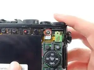
    • Entferne die 2,5 mm lange Kreuzschlitzschraube #000 unten am Sucher.

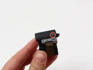
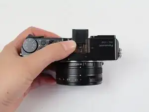
    • Ziehe das schwarze Kunststoffteil vom Sucher ab.

    This was a 4.5 mm screw.

    pinkerton.farm -

    To pull it off, pull the bottom side first. Removing this cover offers the advantage to clean the viewfinder glass.

    Stefan -

    This screw has a coarser thread pitch than the others

    Ren Yuthok -

  6. gPRtPhAdM2ILbnQl
    gPRtPhAdM2ILbnQl
    FtP4fLv5KibXFEEJ
    vmJ6FTnvWQR1I1bo
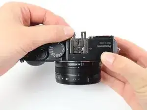
    • Schiebe das schwarze Kunststoffteil heraus. Es dient als Abstandshalter für die aufsetzbare Linse oben auf der Kamera.

    • Unter diesem Kunststoffteil befindet sich eine schmale Metalleinlage. Ziehe dieses Teil vom Objektiv weg heraus.

    • Eventuell musst du das Teil am Ende mit einem geeigneten Werkzeug (Spudger oder Öffnungswerkzeug) etwas hochheben, um es herausschieben zu können.

  7. YURTry4UmQDGFqMR
    • Manche dieser Schrauben sind mit einem Kleber gesichert, um zu verhindert, dass die Kamera zerlegt werden kann. Drücke beim Herausdrehen fest auf den Schraubendreher und arbeite langsam, damit die Schraubenköpfe nicht beschädigt werden.

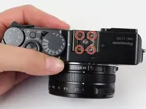
    • Wenn die Metalleinlage weg ist, werden vier Kreuzschlitzschrauben sichtbar. Entferne die vier 7,1 mm Kreuzschlitzschrauben #000.

  8. hKoYyqAMN5tpVIPF
    • Die Rückseite ist eventuell verklebt. Arbeite vorsichtig, damit keine Flachbandkabel darunter beschädigt werden.

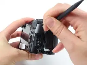
    • Beginne an der oberen rechten Seite des LCDs und heble die Rückseite der Kamera mit einem Spudger ab.

    The top right is stuck that i cannot pry off the back plate, is there a screw or some adhesive ?

    parentshyps -

    there's a screw that mount the 4-way scroll wheel to the back plate, DO NOT try to pry off the back plate as shown in the photo by force.

    You should pry off the back plate with the scroll wheel, and then detach the flat cable on the camera.

    jenghanhsieh -

    My device had a additional screw underneath the rubber piece. I had to remove the rubber piece partially and then I could remove the screw (silver one with a big, flat head). Now I could continue to remove the back. Also the 4-way scroll wheel and buttons are screwed to the back plate, so two screws this guide doesnt show.

    Rincewind -

    Agree with the comments above. The screw pictured in Step 9 is behind the rubber thumb rest in step 8 and must be removed before the back can be taken off. Also, the buttons are attached to the back plate by a screw, so will come off with the back plate. They are attached to the motherboard with a ribbon cable that must be disconnected.

    Damon Schreiber -

    I think this is the difference between the LX100 and the LX100S versions. I had the same challenges above.

    Trigg Bowlin -

    I also had a screw under the rubber thumb pad. And the rubber thumb pad should not be completely removed as it was attached to the back plate via a small screw from the inside of the back of the camera.

    Looking at the back of the camera, only remove the left (thinner) side of the rubber thumb pad in order to get access to the hidden screw. This screw needs to be completely removed before prying the back off the camera.

    pinkerton.farm -

    Im struggling to get it off where the Fn3 and Fn2 buttons are, any suggestions?

    ellie1 -

    for the ZIF cable connectors, DO NOT LIFT ON THE WHITE PART. The ZIF connectors here have a black bar on the back that you left up on.

    Ren Yuthok -

    again , screw behind thumbrest needs to be removed , certainly on the LX100 mk 1 variant , otherwise a really helpful article !

    swlewthwaite -

  9. CpPQLhhfo3EQVQO2
    • Entferne die 7,5 mm lange Kreuzschlitzschraube #000, mit der die Metallabschirmung befestigt ist.

    I had to remove this screw in the previous step, otherwise I couldn't remove the back.

    Rincewind -

    I agree with Rincewind. This screw was hidden under the thin part of the rubber thumb pad on the back of the camera and it needed to be removed in the previous step.

    pinkerton.farm -

    same with me, please update this step, otherwise some users might strip the screw forcefully

    Kevin Darras -

    It’s documented in the service manual that you have to remove this screw before you take off the back cover, It can be accessed by lifting the left side of the rubber thumb rest. There’s some adhesive beneath that rubber.

    Stefan -

    Do you have a copy of service manual? I only need the part regarding tightening those torx screws. Thx

    Zao Pao -

    I also needed to remove this screw before opening the case. The navigation buttons across the right back-side of the camera, as well as the top row of buttons (fn2, fn3, etc) were all connected to the back panel. Be careful not to tear that ribbon cable when removing the back. Lift slowly. — On a side note. I could really use another one of theses screws (the one in this step) as mine has stripped after a few removals. Anyone know how or where I could get one of these?

    tdeckard2000 -

  10. n4RVHFJ3gwCSPLOM
    n4RVHFJ3gwCSPLOM
    kIYjxARaYI6VTgmZ
    SCdLlitOiYGaNQPt
    • Hebe das LCD vom Gerät weg.

    • Heble die silberne Metallplatte mit einem Spudger ab.

    • Löse das Flachbandkabel ab, mit dem das LCD am Motherboard angeschlossen ist.

    • Wenn nötig, kannst du das Flachbandkabel mit einem Spudger aus seinem Anschluss heraushebeln.

    • Entferne das LCD.

    You have to lift the small black latch to open the socket for the ribbon cable. The cable then comes out easily.

    Stefan -

    If you want to replace the broken battery door, you proceed until this step and then you are able to do it.

    Ferdinand Hami -

    I pulled out the connector and try to push it back in and was too tight. It did not work, there is black bar on the backside that had to be clicked up from the back for release to put the lcd connector back in easier. This would prob be better to do before removing the connector to loosen it first. Camera is fixed and working now. Did not replace lcd but reconnected which fixed the grey pixelated screen.

    Jaime Escher -

  11. NfX55JX4JpKGCgw2
    • Um manche der Flachbandkabel abzutrennen, benötigst du möglicherweise einen Spudger und eine Pinzette, um zu vermeiden, dass sie reißen.

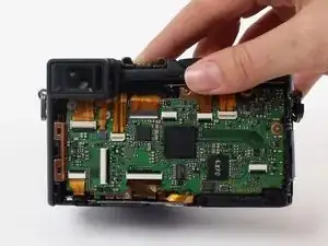
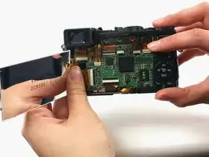
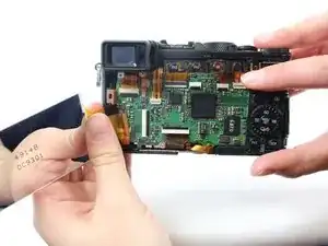
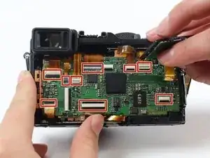
    • Es sind neun Flachbandkabel/ZIF-Anschlüsse zu sehen. Trenne sie ab, indem du die Sicherungsbügel hochklappst und die Kabel herausziehst.

    • Hinter den sichtbaren Kabeln befinden sich noch zwei weitere in der oberen linken Ecke der Hauptplatine.

    • Wenn du noch mehr über das Abtrennen von ZIF-Anschlüsse wissen willst, dann lies diese Anleitung.

    All of these connectors have a backflip mechanism (a bar is flipped up to allow insertion or removal of the ribbon cable) except the smallest two. One is pictured in this photo second from left on top, and the other is hidden on the top underneath other cables. These two connectors have no locking mechanism. The cable is simply pulled directly out.

    Damon Schreiber -

    The step is fine but doesn't underline an important deal: when you have to put the cables back it's a nightmare. Be very very carefull putting them back in the original position. The most difficult are the second from left to the top as mentioned by Damon Schreiber in the former comment and another not underlined in the foto that is right close to the top of just mentioned.

    enrycone -

  12. 3Qx1hNYMbZE2os4e
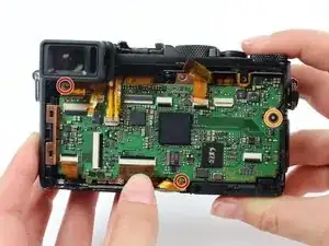
    • Entferne die beiden 4,5 mm Kreuzschlitzschrauben #000.

    • Entferne eine 2,5 mm Kreuzschlitzschraube #000.

    The lengths shown for the screws didn’t match my camera. The upper two screws were shorter than the bottom screw in this step. The bottom screw had a coarser thread pitch since it’s screwed into plastic and the top two are screwed into metal.

    Nick Marshall -

    I experienced the same thing as Nick Marshall

    pinkerton.farm -

  13. NY1qhhmRLfuhGAIW
    NY1qhhmRLfuhGAIW
    OBh5Uh4WGLr3cDrV
    • Ziehe den Sucher zu dir hin aus seiner Fassung heraus.

    • Auf dem Foto befindet sich das schwarze Kunststoffteil noch auf dem Sucher. Es sollte beim Ausbau des LCDs bereits entfernt worden sein.

  14. VVETkcfBCAIKkHKf
    VVETkcfBCAIKkHKf
    p3PZRH4ZTH4Piptq
    • Nimm einen Spudger aus Kunststoff und beginne oben an der Hauptplatine mit dem Heraushebeln der Hauptplatine.

    on my model i had to pop out the plastic frame surround holding the flip out hdmi cover - until that was popped out the motherboard would not come - after though - easy as pie...

    Kevin Holmes -

    Yes, I would flip open the AV and HDMI cover and look at how the connectors sit. One is flush and one is a little below the surface. The plastic frame has tabs on the sides that lock into the camera shell. It’s probably best to pull the frame out with the motherboard.

    Nick Marshall -

Abschluss

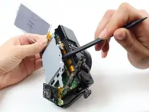
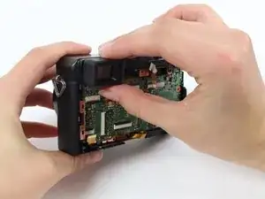
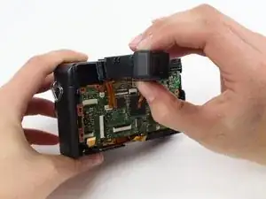
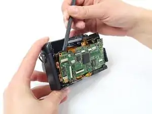
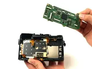
Um dein Gerät wieder zusammenzubauen, folge den Schritten in umgekehrter Reihenfolge.

Sydney Dye

Mitglied seit: 12/01/16

1166 Reputation

Ein Kommentar

This camera is a true dust harvester.

Thanks to this guide I have dared to clean the sensor successfully.

I know that I will have to return to the task in a few months but now I am more sure of the process.

Thanks a lot

guillem garces -